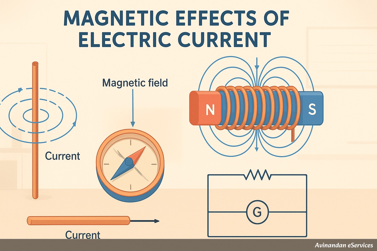
Introduction to Magnetic Effects of Electric Current
Welcome, students! In our previous chapters, we delved into the world of electricity and its heating effects. Now, we venture into another fascinating consequence of electric current: magnetism. Have you ever wondered how an electric fan starts rotating the moment you flip a switch, or how a crane in a junkyard lifts heavy iron scrap without any hooks? The answer lies in the profound relationship between electricity and magnetism, a phenomenon known as the magnetic effect of electric current. This chapter will unravel this connection, which forms the backbone of countless modern technologies, including electric motors, generators, speakers, and MRI machines.
Our journey begins with the accidental yet groundbreaking discovery by Hans Christian Oersted in 1820. He observed that a compass needle deflected when an electric current was passed through a nearby wire. This simple observation proved that electricity and magnetism were not separate phenomena but were intimately related. It laid the foundation for electromagnetism, a field of physics that has revolutionized our world. In this chapter, we will explore magnetic fields, the forces they exert, the principles of electromagnetic induction, and the workings of essential devices like the electric motor and generator. We will also touch upon the crucial aspects of domestic electric circuits and safety measures. Let's begin our exploration of this magnetic world powered by electricity!
Magnetic Field and Field Lines
Before we dive into how electricity creates magnetism, let's first understand what a magnetic field is. We are all familiar with magnets and their ability to attract or repel certain objects like iron, nickel, and cobalt without any physical contact. This 'action at a distance' is possible because of the magnetic field.
What is a Magnetic Field?
A magnetic field is defined as the region or space around a magnet within which its magnetic force can be experienced by another magnet or a magnetic material. When you bring a compass near a bar magnet, its needle (which is a tiny magnet itself) gets deflected. This deflection is due to the force exerted by the bar magnet's magnetic field on the compass needle.
A magnetic field is a vector quantity, meaning it has both magnitude (strength) and direction. The direction of the magnetic field at any point is taken as the direction in which the north pole of a compass needle would point if placed at that point. The SI unit of magnetic field strength is the Tesla (T).
Magnetic Field Lines
To visualize this invisible magnetic field, scientists use a concept called magnetic field lines (or magnetic lines of force). These are imaginary lines used to represent the magnetic field around a magnet. You can visualize them by performing a simple activity: place a bar magnet on a sheet of paper and sprinkle some iron filings around it. Tapping the sheet gently will cause the filings to arrange themselves in a distinct pattern of curved lines, which trace the magnetic field lines.
Properties of Magnetic Field Lines
Magnetic field lines have several distinct and important properties that help us understand the nature of a magnetic field:
- Origin and Termination: By convention, magnetic field lines are considered to emerge from the North pole of a magnet and enter its South pole. They then travel through the magnet from the South pole to the North pole, completing a closed loop.
- Closed Continuous Curves: Unlike electric field lines which can start and end on charges, magnetic field lines always form closed and continuous loops. This implies that isolated magnetic poles (monopoles) do not exist.
- Direction: The direction of the magnetic field at any point is given by the tangent drawn to the field line at that point. This is the same direction a compass needle would align itself with.
- Strength Representation: The relative strength of the magnetic field is shown by the degree of closeness of the field lines. Where the field lines are crowded (closer together), the magnetic field is strong (e.g., near the poles). Where they are far apart, the field is weak.
- Non-Intersection: Two magnetic field lines can never intersect each other. If they were to intersect, it would mean that at the point of intersection, a compass needle would point in two different directions simultaneously, which is physically impossible.
Magnetic Field due to a Current-Carrying Conductor
Oersted's experiment was a turning point. It established that an electric current flowing through a conductor produces a magnetic field around it. This effect is why a compass needle deflects near a current-carrying wire. Let's explore the pattern of this magnetic field for different types of conductors.
Magnetic Field due to a Current through a Straight Conductor
Imagine a long, straight copper wire carrying an electric current. The magnetic field lines around it are in the form of concentric circles, with the wire at the center. The plane of these circles is perpendicular to the wire. If the current flows upwards, the field lines are counter-clockwise, and if the current flows downwards, they are clockwise.
To easily determine the direction of these magnetic field lines, we use the Right-Hand Thumb Rule (also known as Maxwell's Corkscrew Rule).
Right-Hand Thumb Rule: Imagine you are holding a current-carrying straight conductor in your right hand such that your thumb points in the direction of the current. Then, the direction in which your fingers curl around the conductor gives the direction of the magnetic field lines.
The strength of the magnetic field (B) produced by a straight current-carrying wire depends on two factors:
- It is directly proportional to the strength of the current (I) flowing through the wire. (B ∝ I)
- It is inversely proportional to the distance (r) from the wire. (B ∝ 1/r)
Magnetic Field due to a Current through a Circular Loop
Now, what if we bend the straight wire into a circular loop and pass a current through it? The magnetic field lines are still concentric circles near the wire, but as we move towards the center of the loop, the arcs of these circles become larger. At the very center of the loop, the magnetic field line appears as a straight line, perpendicular to the plane of the loop.
Every point on the wire loop contributes to the magnetic field inside the loop, and their directions add up. This makes the magnetic field inside the loop stronger and more uniform, especially at the center. The strength of the magnetic field produced by a current-carrying circular loop depends on:
- It is directly proportional to the current (I).
- It is inversely proportional to the radius (r) of the circular loop.
- It is directly proportional to the number of turns (N) in the coil. If we have a coil with 'N' turns, the field produced is N times larger than that produced by a single loop.
Magnetic Field due to a Current in a Solenoid
A solenoid is a long coil containing a large number of close turns of insulated copper wire, usually in the shape of a cylinder. When an electric current is passed through it, a magnetic field is produced. The magnetic field of a current-carrying solenoid is very similar to that of a bar magnet.
One end of the solenoid behaves like a magnetic North pole, while the other end behaves like a South pole. The field lines outside the solenoid emerge from the North pole and enter the South pole. Inside the solenoid, the magnetic field lines are nearly parallel straight lines. This indicates that the magnetic field is uniform and strong inside the solenoid. This property makes solenoids very useful for creating strong, controlled magnetic fields.
Electromagnet
An electromagnet is a temporary magnet that can be easily turned on or off. It is typically made by placing a soft iron rod (called a core) inside a solenoid. When current flows through the solenoid, the soft iron core becomes strongly magnetized. When the current is switched off, it loses its magnetism almost completely. The strength of an electromagnet can be increased by increasing the current, increasing the number of turns in the coil, or using a more suitable core material. Electromagnets are used in electric bells, cranes, and medical equipment like MRI scanners.
| Property | Electromagnet | Permanent Magnet |
|---|---|---|
| Nature | Temporary magnet; magnetism exists only when current flows. | Permanent magnet; magnetism is constant. |
| Strength | Can be varied by changing the current or number of turns. Can be very strong. | Fixed and generally weaker than strong electromagnets. |
| Polarity | Can be reversed by reversing the direction of the current. | Fixed and cannot be changed. |
| Material | Made of soft iron, which has low retentivity. | Made of steel or alloys like Alnico, which have high retentivity. |
Force on a Current-Carrying Conductor in a Magnetic Field
We've established that an electric current creates a magnetic field. What happens when we place a wire carrying a current into an \texternal magnetic field, say, from a permanent magnet? The two magnetic fields—one from the current and one from the magnet—will interact. This interaction results in a force being exerted on the wire.
French scientist André-Marie Ampère suggested that if a current can exert a force on a magnet (like a compass needle), then a magnet must also exert an equal and opposite force on the current-carrying conductor. This can be demonstrated with a simple experiment where a small aluminium rod, suspended in a strong horseshoe magnet, is deflected or 'kicked' when a current passes through it. Reversing the direction of the current reverses the direction of the force. This principle is the cornerstone of how electric motors work.
The magnitude of the force experienced by the conductor depends on:
- The strength of the current (I).
- The length of the conductor (l) within the magnetic field.
- The strength of the \texternal magnetic field (B).
Fleming's Left-Hand Rule
To find the direction of the force (or motion) on the conductor, we use a handy tool called Fleming's Left-Hand Rule.
Fleming's Left-Hand Rule: Stretch the thumb, forefinger (index finger), and middle finger of your left hand so that they are mutually perpendicular to each other. If the Forefinger points in the direction of the magnetic Field, and the middle finger points in the direction of the Current, then the Thumb will point in the direction of the Thrust or Motion (force) on the conductor. (A common mnemonic is Father-Mother-Child for Force-Field-Current).
Electric Motor
The principle of a force acting on a current-carrying conductor in a magnetic field is put to practical use in devices like electric fans, mixers, and washing machines. All these contain an electric motor.
An electric motor is a rotating device that converts electrical energy into mechanical energy (the energy of motion).
Principle of an Electric Motor
An electric motor works on the principle that when a rectangular coil carrying current is placed in a magnetic field, it experiences a force (or torque) which rotates it continuously.
Construction of a DC Motor
A simple DC (Direct Current) motor consists of the following key parts:
- Armature Coil: A rectangular coil (let's call it ABCD) made of many turns of insulated copper wire wound on a soft iron core.
- Strong Magnet: Two strong permanent magnet poles (North and South) that create a uniform magnetic field in the region where the coil rotates.
- Split-Ring Commutator: This is the key component for continuous rotation. It consists of a metallic ring split into two halves (P and Q). The two ends of the armature coil are connected to these two halves. The commutator rotates along with the coil.
- Brushes: Two stationary carbon brushes (X and Y) that press against the two halves of the commutator. They act as the point of contact to supply current from the battery to the rotating coil.
- Battery: A source of direct current.
Working of a DC Motor
Let's trace the working of the motor for one full rotation:
- Current from the battery enters the coil through brush X, flows through the coil along the path ABCD, and exits through brush Y.
- Consider the arm AB of the coil. The current flows from A to B. The magnetic field is from the North pole to the South pole. Applying Fleming's Left-Hand Rule, we find that the force on arm AB pushes it downwards.
- Now consider arm CD. The current flows from C to D (opposite to AB). Applying Fleming's Left-Hand Rule again, we find the force on arm CD pushes it upwards.
- These two equal and opposite forces acting on the arms of the coil form a 'couple' and cause the coil to rotate in an anti-clockwise direction.
- The coil continues to rotate until it reaches the vertical position. At this point, the brushes X and Y touch the gap between the split rings P and Q, and the current to the coil is cut off. However, due to its inertia of motion, the coil overshoots the vertical position.
- As the coil moves past the vertical, the split rings change contact. Ring P now touches brush Y, and ring Q touches brush X. This masterfully reverses the direction of current in the coil. The current now flows along the path DCBA.
- Due to this reversal, the force on arm AB is now upwards, and the force on arm CD is downwards. This ensures the coil continues to rotate in the same anti-clockwise direction.
- This process of current reversal by the commutator happens every half rotation, resulting in a continuous, smooth rotation of the coil as long as the current is supplied.
Commercial motors are more powerful as they use an electromagnet instead of a permanent magnet, have a larger number of turns in the coil, and use a soft iron core on which the coil is wound (the core and coil together are called an armature).
Electromagnetic Induction (EMI)
We've seen that an electric current can produce a magnetic field. Michael Faraday, a brilliant experimental physicist, wondered about the reverse: can a magnetic field produce an electric current? In 1831, he proved that it could. This phenomenon is called Electromagnetic Induction (EMI).
Electromagnetic Induction is the phenomenon of producing an induced electric current in a closed circuit or coil by changing the magnetic field associated with it. The current produced by this phenomenon is called the induced current.
Faraday demonstrated this with simple experiments:
- Experiment 1 (Magnet and Coil): He took a coil of wire connected to a galvanometer (an instrument to detect small currents). When a bar magnet was held stationary near the coil, there was no deflection. However, when the North pole of the magnet was moved towards the coil, the galvanometer showed a momentary deflection, indicating an induced current. When the magnet was moved away, the galvanometer again deflected, but in the opposite direction. The faster the relative motion between the magnet and the coil, the larger the induced current.
- Experiment 2 (Two Coils): He used two coils, a primary coil connected to a battery and a secondary coil connected to a galvanometer. When a steady current flowed in the primary coil, there was no current in the secondary. But the moment the current was switched on or off in the primary coil, the galvanometer connected to the secondary coil showed a momentary deflection. This is because switching the current on or off changes the magnetic field associated with the primary coil, and this changing field induces a current in the nearby secondary coil.
Fleming's Right-Hand Rule
Just as we have a rule for the force on a conductor, we have a rule to find the direction of the induced current. This is Fleming's Right-Hand Rule, and it is used for generators.
Fleming's Right-Hand Rule: Stretch the thumb, forefinger, and middle finger of your right hand so that they are mutually perpendicular. If the Thumb points in the direction of the Motion of the conductor and the Forefinger points in the direction of the magnetic Field, then the middle finger will show the direction of the Induced Current.
Electric Generator
The principle of electromagnetic induction is the foundation for the electric generator, a device that produces electricity for our homes and industries.
An electric generator is a device that converts mechanical energy into electrical energy.
Principle of an Electric Generator
An electric generator works on the principle of electromagnetic induction. When a conductor (in the form of a coil) is rotated in a magnetic field, the magnetic field lines linked with the coil change, which induces an electric current in the coil.
Construction and Working of an AC Generator
The construction of a simple AC (Alternating Current) generator is very similar to that of a DC motor, with one crucial difference in the way the current is drawn from the coil.
Construction: It has an armature coil (ABCD), strong magnets, and brushes. However, instead of a split-ring commutator, it uses two full metallic rings called slip rings (R1 and R2). Each end of the coil is connected to a separate slip ring. The stationary brushes (B1 and B2) maintain contact with these rotating slip rings.
Working:
- The armature coil ABCD is rotated mechanically (by wind, water, steam turbine, etc.) within the magnetic field. Let's assume it rotates clockwise.
- As it rotates, arm AB moves up and arm CD moves down, cutting the magnetic field lines.
- Applying Fleming's Right-Hand Rule to arm AB (motion up, field N to S), the induced current flows from A to B. In arm CD (motion down), the induced current flows from C to D. The current flows out through brush B2 and into brush B1 in the \texternal circuit.
- After half a rotation, the positions of the arms are interchanged. Arm AB now moves down, and arm CD moves up.
- Applying the rule again, the direction of induced current in the arms reverses. It now flows from B to A and D to C. In the \texternal circuit, the current now flows out through brush B1 and into brush B2.
- Thus, after every half rotation, the polarity of the current in the \texternal circuit changes. This type of current, which reverses its direction periodically, is called Alternating Current (AC).
AC vs DC
- Alternating Current (AC): An electric current that reverses its direction after equal intervals of time. In India, the AC reverses its direction every 1/100 second, so its frequency is 50 Hz (50 cycles per second). A significant advantage of AC is that it can be transmitted over long distances with minimal loss of energy.
- Direct Current (DC): An electric current that always flows in a single direction. A battery is a source of DC.
To create a DC Generator, we simply replace the slip rings with a split-ring commutator, just like in a DC motor. The commutator ensures that the current in the \texternal circuit always flows in the same direction, even though the current in the coil reverses every half rotation.
Domestic Electric Circuits
The electricity generated at power stations reaches our homes through a network of cables. Let's look at the basic layout of a domestic circuit.
Electricity is supplied to our homes through two main wires. These are:
- Live Wire (or Phase wire): This wire has a red insulation cover and is at a high potential of 220 Volts (in India).
- Neutral Wire: This wire has a black insulation cover and is at or near zero potential. The potential difference between the live and neutral wire is 220 V.
In our homes, all appliances like bulbs, fans, and sockets are connected in parallel across the live and neutral wires. This parallel connection has several advantages:
- Each appliance gets the same, full voltage of 220 V.
- Operating one appliance does not affect the operation of others.
- If one appliance gets damaged, the others continue to work.
Electrical Safety Devices and Concepts
Electricity is useful but can be \textremely dangerous if not handled properly. Domestic circuits include several safety features.
Earth Wire: This wire has a green insulation cover and is a crucial safety measure. It is connected to a large metal plate buried deep in the earth near the house. The metallic body of high-power appliances (like refrigerators, washing machines, and electric irons) is connected to this earth wire. If, by fault, the live wire touches the metallic casing of the appliance, a very large current flows through the earth wire to the ground, instead of through the user's body. This massive current flow blows the fuse and disconnects the appliance, saving the user from a potentially fatal electric shock.
Electric Fuse: A fuse is a safety device used to protect the circuit and appliances from excessive current. It consists of a piece of wire made of an alloy with a low melting point (e.g., a tin-lead alloy). It is always connected in series with the live wire. If the current in the circuit exceeds a safe value, the fuse wire heats up (due to the Joule effect), melts, and breaks the circuit, stopping the flow of current.
Overloading: This occurs when too many high-power appliances are connected to a single socket, drawing a current greater than the circuit's capacity. This can cause the wires to overheat and potentially start a fire. A fuse or MCB protects against overloading by breaking the circuit.
Short-Circuiting: This happens when the live wire and the neutral wire come into direct contact with each other, for example, due to damaged insulation. When this occurs, the resistance of the circuit becomes almost zero. According to Ohm's law (I = V/R), this leads to an \textremely large current flowing through the circuit, which can cause sparks and fire. The fuse or MCB immediately breaks the circuit to prevent damage.
Important Questions and Answers
Here are some solved questions to help you revise the concepts from this chapter.
Question 1: Why does a compass needle get deflected when brought near a bar magnet?
Answer: A compass needle is itself a tiny permanent magnet with a North and a South pole. When it is brought into the magnetic field of a bar magnet, the field exerts a force on the poles of the compass needle. This force creates a turning effect (torque) on the needle, causing it to align itself with the direction of the magnetic field lines at that point. This alignment results in the deflection of the compass needle.
Question 2: State Fleming's left-hand rule.
Answer: Fleming's left-hand rule is used to determine the direction of the force experienced by a current-carrying conductor placed in a magnetic field. The rule states: Stretch the thumb, forefinger, and the middle finger of your left hand such that they are mutually perpendicular to each other. If the forefinger points in the direction of the magnetic field and the middle finger points in the direction of the electric current, then the thumb will indicate the direction of the force or motion of the conductor.
Question 3: Explain the principle and working of an electric motor.
Answer: Principle: An electric motor works on the principle that a current-carrying conductor placed in a magnetic field experiences a force, and if the conductor is in the form of a coil, this force can produce a continuous rotation. Working: An electric motor consists of a rectangular coil (armature) placed in a magnetic field. Current is passed through the coil via brushes and a split-ring commutator. According to Fleming's left-hand rule, the two opposite sides of the coil carrying current in opposite directions experience forces in opposite directions. These two forces form a couple that rotates the coil. After half a rotation, the split-ring commutator reverses the direction of the current in the coil. This reverses the direction of forces on the sides of the coil, ensuring that the coil continues to rotate in the same direction. This process repeats, converting electrical energy from the battery into the continuous mechanical energy of rotation.
Question 4: What is the function of an earth wire? Why is it necessary to earth metallic appliances?
Answer: The function of an earth wire is to provide a safety measure against electric shock. It provides a low-resistance path for the current to flow to the earth in case of an electrical fault. It is necessary to earth metallic appliances (like refrigerators, electric irons, etc.) because if the insulation of the live wire inside the appliance wears out and it touches the metallic body, the body becomes live. Anyone touching the appliance would get a severe electric shock. However, if the appliance is earthed, this large leakage current flows directly to the earth through the earth wire. This heavy current blows the fuse or trips the MCB, disconnecting the power supply and protecting the user.
Question 5: When is the force experienced by a current-carrying conductor placed in a magnetic field the largest?
Answer: The force experienced by a current-carrying conductor placed in a magnetic field is largest (maximum) when the direction of the current is perpendicular (at an angle of 90°) to the direction of the magnetic field. The force is zero when the direction of the current is parallel to the direction of the magnetic field.
Chapter Summary
Let's quickly recap the key concepts we've learned in this chapter:
- A magnet is surrounded by a magnetic field, a region where its force can be detected.
- Magnetic field lines are used to visualize a magnetic field. They form closed loops, emerge from the North pole and enter the South pole, and never intersect.
- An electric current flowing through a conductor always produces a magnetic field around it.
- The magnetic field around a straight conductor consists of concentric circles, whose direction is given by the Right-Hand Thumb Rule.
- A current-carrying solenoid behaves like a bar magnet, with a strong, uniform magnetic field inside it.
- An electromagnet is a temporary magnet made by passing current through a coil wound on a soft iron core.
- A conductor carrying current experiences a force when placed in a magnetic field. The direction of this force is given by Fleming's Left-Hand Rule.
- An electric motor is a device that uses this principle to convert electrical energy into mechanical energy. A split-ring commutator is essential for its continuous rotation.
- Electromagnetic Induction (EMI) is the phenomenon of inducing an electric current in a coil by changing the magnetic field associated with it.
- The direction of the induced current is given by Fleming's Right-Hand Rule.
- An electric generator works on the principle of EMI to convert mechanical energy into electrical energy. AC generators use slip rings, while DC generators use a split-ring commutator.
- Domestic electric circuits typically consist of a live wire (red), a neutral wire (black), and an earth wire (green).
- Safety devices like fuses and earthing, along with awareness about overloading and short-circuiting, are crucial for preventing electrical accidents.